How can we Cabling the Console Connection in this article is explaining how to cabling console connection in PC using switches and USB.
The physical console connection, both old and new, uses three main components: the physical console port on the switch, a physical interface on the PC, and a cable that works with the console and serial ports. However, the physical cabling details have changed slowly over time, mainly due to advances and changes with serial interfaces on PC hardware. For this next topic, the text looks at three cases: newer connectors on both the PC and therefore the switch, older connectors on both, and a 3rd case with the newer (USB) connector on the PC but with an older connector on the switch. More modern PC and switch hardware use a well-known standard USB cable for the console connection. Cisco has been including USB ports as console ports in newer routers and switches also . All you’ve got to do is check out the switch to form sure you’ve got the correct sort of USB cable end to match the USB console port. within the simplest form, you’ll use any USB port on the PC, with a USB cable, connected to the USB console port on the switch or router, as shown on the far right side of Figure 6-3.
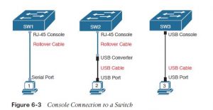
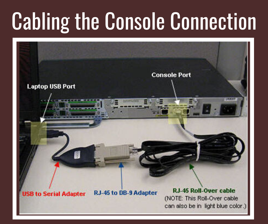
Older console connections use a PC serial port that pre-dates USB, a UTP cable, and an RJ-45 console port on the switch, as shown on the left side of Figure 6-3. The PC serial port typically has a D-shell connector (roughly rectangular) with nine pins (often called a DB-9). The console port seems like any Ethernet RJ-45 port (but is usually colored in blue and with the word “console” beside it on the switch). The cabling for this older-style console connection are often simple or require some effort, depending on what cable you use. you’ll use the purpose-built console cable that ships with new Cisco switches and routers and not believe the small print . However, you’ll make your own cable with a typical serial cable (with a connector that matches the PC), a typical RJ-45 to DB-9 converter plug, and a UTP cable. However, the UTP cable doesn’t use the same pinouts as Ethernet; instead, the cable uses rollover cable pinouts instead of any of the standard Ethernet cabling pinouts. The rollover pinout uses eight wires, rolling the wire at pin 1 to pin 8, pin 2 to pin 7, pin 3 to pin 6, and so on. because it seems , USB ports became common on PCs before Cisco began commonly using USB for its console ports. So, you also need to be able to use a PC that has only a USB port and not an old interface , but a router or switch that has the older RJ-45 console port (and no USB console port). the middle of Figure 6-3 shows that case. to connect such a PC to a router or switch console, you would like a USB converter that converts from the older console cable to a USB connector, and a rollover UTP cable, as shown within the middle of Figure 6-3.
Also Read : How to Configuring Cisco IOS Software
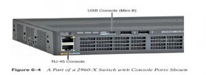
The newer 2960-X series, as an example , supports both the older RJ-45 console port and a USB console port. Figure 6-4 points to the 2 console ports; you’d use just one or the opposite . Note that the USB console port uses a mini-B port instead of the more commonly seen rectangular standard USB port.
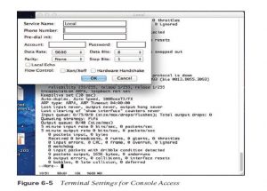
After the PC is physically connected to the console port, a terminal emulator software package must be installed and configured on the PC. The terminal emulator software treats all data as text. It accepts the text typed by the user and sends it over the console connection to the switch. Similarly, any bits coming into the PC over the console connection are displayed as text for the user to read. The emulator must be configured to use the PC’s interface to match the settings on the switch’s console port settings. The default console port settings on a switch are as follows. Note that the last three parameters are mentioned collectively as 8N1:
- 9600 bits/second
- No hardware flow control
- 8-bit ASCII
- No parity bits
- 1 stop bit
Figure 6-5 shows one such terminal emulator. The image shows the window created by the emulator software within the background, with some output of a show command. The foreground, within the upper left, shows a settings window that lists the default console settings as listed just before this paragraph.
Questions related to this topic
- Which type of cable would I use to connect a console port on a router to a COM port on a PC?
- How do you connect a console port to a switch?
- What type of cable is used to connect the Ethernet interface on a host PC to the Ethernet interface on a switch?
- What type of cable is required to connect to the console port on a Cisco device?
This Blog Article is posted by
Infosavvy, 2nd Floor, Sai Niketan, Chandavalkar Road Opp. Gora Gandhi Hotel, Above Jumbo King, beside Speakwell Institute, Borivali West, Mumbai, Maharashtra 400092
Contact us – www.info-savvy.com