This blog is on TCP/IP networking model in that Overview has given as well as there different layer has been explained.
Overview
The TCP/IP model both defines and references a large collection of protocols that allow computers to communicate. To define a protocol, TCP/IP uses documents called Requests For Comments (RFC). (You can find these RFCs using any online search engine.) The TCP/IP model also avoids repeating work already done by another standards body or vendor consortium by simply pertaining to standards or protocols created by those groups. for instance , the Institute of Electrical and Electronic Engineers (IEEE) defines Ethernet LANs; the TCP/IP model doesn’t define Ethernet in RFCs, but refers to IEEE Ethernet as an option. a simple comparison are often made between telephones and computers that use TCP/IP. You attend the shop and buy a phone from one among a dozen different vendors. once you get home and connect the phone to an equivalent cable during which your old phone was connected, the new phone works. The phone vendors know the standards for phones in their country and build their phones to match those standards. Similarly, once you buy a new computer today, it implements the TCP/IP model to the point that you simply can usually take the pc out of the box, connect all the proper cables, turn it on, and it connects to the network. you’ll use an internet browser to attach to your favorite website. How? Well, the OS on the pc implements parts of the TCP/IP model. The Ethernet card, or wireless LAN card, inbuilt to the pc implements some LAN standards referenced by the TCP/IP model. In short, the vendors that created the hardware and software implemented TCP/IP. To help people understand a networking model, each model breaks the functions into a little number of categories called layers. Each layer includes protocols and standards that relate thereto category of functions. TCP/IP actually has two alternative models, as shown in Figure 1-4.
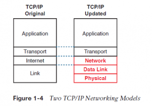 The model on the left shows the first TCP/IP model listed in RFC 1122, which breaks TCP/IP into four layers. the top two layers focus more on the applications that require to send and receive data. the bottom layer focuses on how to transmit bits over each individual link, with the web layer focusing on delivering data over the whole path from the first sending computer to the ultimate destination computer. The TCP/IP model on the proper shows the more common terms and layers used when people talk about TCP/IP today. It expands the first model’s link layer into two separate layers: data link and physical (similar to the lower two layers of the OSI model). Also, many of us commonly use the word “Network” rather than “Internet” for one layer.
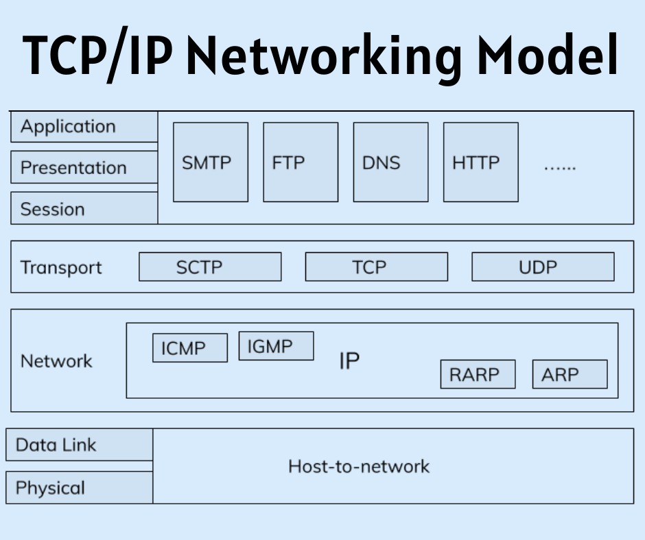
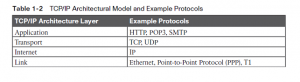
Many of you’ll have already heard of several TCP/IP protocols, just like the examples listed in Table 1-2. Most of the protocols and standards during this table are going to be explained in additional detail as you work through this book. Following the table, this section takes a closer look at the layers of the TCP/IP model.
 TCP/IP Application Layer
TCP/IP application layer protocols provide services to the application software running on a computer. the application layer doesn’t define the application itself, but it defines services that applications need. for instance , application protocol HTTP defines how web browsers can pull the contents of an internet page from an internet server. In short, the application layer provides an interface between software running on a computer and therefore the network itself. Arguably, the foremost popular TCP/IP application today is that the web browser. Many major software vendors either have already changed or are changing their application software to support access from a web browser. And thankfully, using a web browser is easy: you begin a web browser on your computer and choose a website by typing the name of the web site , and therefore the website appears.
HTTP Overview
What really happens to permit that website to seem on your web browser? Imagine that Bob opens his browser. His browser has been configured to automatically ask for web server Larry’s default website , or home page. the overall logic seems like Figure 1-5.
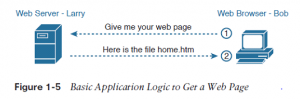
So, what really happened? Bob’s initial request actually asks Larry to send his home page back to Bob. Larry’s web server software has been configured to understand that the default website is contained during a file called home.htm. Bob receives the file from Larry and displays the contents of the file in Bob’s browser window.
HTTP Protocol Mechanisms
Taking a closer look, this instance shows how applications on each endpoint computer— specifically, the web browser application and web server application—use a TCP/IP application layer protocol. to make the request for a web page and return the contents of the web page, the applications use the Hypertext Transfer Protocol (HTTP).
HTTP didn’t exist until Tim Berners-Lee created the primary browser and web server within the early 1990s. Berners-Lee gave HTTP functionality to invite the contents of sites , specifically by giving the online browser the power to request files from the server and giving the server how to return the content of these files. the general logic matches what was shown in Figure 1-5; Figure 1-6 shows an equivalent idea, but with details specific to HTTP.
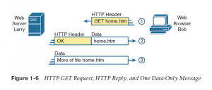
To get the online page from Larry, at
Step 1, Bob sends a message with an HTTP header. Generally, protocols use headers as an area to put information used by that protocol. This HTTP header includes the request to “get” a file. The request typically contains the name of the file (home.htm, during this case), or if no filename is mentioned, the web server assumes that Bob wants the default website .
Step 2 in Figure 1-6 shows the response from web server Larry. The message begins with an HTTP header, with a return code (200), which means something as simple as “OK” returned within the header. HTTP also defines other return codes in order that the server can tell the browser whether the request worked. (Here is another example: If you ever searched for an internet page that wasn’t found, then received an HTTP 404 “not found” error, you received an HTTP return code of 404.) The second message also includes the primary a part of the requested file.
Step 3 in Figure 1-6 shows another message from web server Larry to browser Bob, but this point without an HTTP header. HTTP transfers the info by sending multiple messages, each with a part of the file. instead of wasting space by sending repeated HTTP headers that list the same information, these additional messages simply omit the header.
TCP/IP Transport Layer
Although many TCP/IP application layer protocols exist, the TCP/IP transport layer includes a smaller number of protocols. the 2 most ordinarily used transport layer protocols are the Transmission Control Protocol (TCP) and therefore the User Datagram Protocol (UDP). Transport layer protocols provide services to the application layer protocols that reside one layer higher within the TCP/IP model. How does a transport layer protocol provide a service to a higher-layer protocol? This section introduces that general concept by focusing on one service provided by TCP: error recovery. Later chapters examine the transport layer in additional detail and discuss more functions of the transport layer.
TCP Error Recovery Basics
To appreciate what the transport layer protocols do, you want to think about the layer above the transport layer, the application layer. Why? Well, each layer provides a service to the layer above it, just like the error-recovery service provided to application layer protocols by TCP.
For example, in Figure 1-5, Bob and Larry used HTTP to transfer the home page from web server Larry to Bob’s browser . But what would have happened if Bob’s HTTP GET request had been lost in transit through the TCP/IP network? Or, what would have happened if Larry’s response, including the contents of the home page, had been lost? Well, as you would possibly expect, in either case, the page wouldn’t have shown up in Bob’s browser.
TCP/IP needs a mechanism to ensure delivery of data across a network. Because many application layer protocols probably want a way to guarantee delivery of data across a network, the creators of TCP included an error-recovery feature. To recover from errors, TCP uses the concept of acknowledgments. Figure 1-7 outlines the basic idea behind how TCP notices lost data and asks the sender to try again.
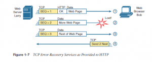
Figure 1-7 shows web server Larry sending an internet page to browser Bob, using three separate messages. Note that this figure shows an equivalent HTTP headers as Figure 1-6, but it also shows a TCP header. The TCP header shows a sequence number (SEQ) with each message. during this example, the network features a problem, and therefore the network fails to deliver the TCP message (called a segment) with sequence number 2. When Bob receives messages with sequence numbers 1 and three , but doesn’t receive a message with sequence number 2, Bob realizes that message 2 was lost. That realization by Bob’s TCP logic causes Bob to send a TCP segment back to Larry, asking Larry to send message 2 again.
Also Read:- Introduction of OSI Networking Model
Same-Layer and Adjacent-Layer Interactions
The example in Figure 1-7 also demonstrates a function called adjacent-layer interaction, which refers to the concepts of how adjacent layers during a networking model, on an equivalent computer, work together. during this example, the higher-layer protocol (HTTP) wants error recovery, and therefore the higher layer uses the next lower-layer protocol (TCP) to perform the service of error recovery; the lower layer provides a service to the layer above it. Figure 1-7 also shows an example of a similar function called same-layer interaction. When a specific layer on one computer wants to communicate with an equivalent layer on another computer, the 2 computers use headers to carry the information that they need to speak . for instance , in Figure 1-7, Larry set the sequence numbers to 1, 2, and three in order that Bob could notice when a number of the data didn’t arrive. Larry’s TCP process created that TCP header with the sequence number; Bob’s TCP process received and reacted to the TCP segments.
Table 1-3 summarizes the key points about how adjacent layers work together on one computer and the way one layer on one computer works with an equivalent networking layer on another computer.
TCP/IP Network Layer
The application layer includes many protocols. The transport layer includes fewer protocols, most notably, TCP and UDP. The TCP/IP network layer includes alittle number of protocols, but just one major protocol: the internet Protocol (IP) . In fact, the name TCP/IP is just the names of the 2 commonest protocols (TCP and IP) separated by a /.
IP provides several features, most significantly , addressing and routing. This section begins by comparing IP’s addressing and routing with another commonly known system that uses addressing and routing: the postal service. Following that, this section introduces IP addressing and routing. (More details follow in Chapter 4, “Fundamentals of IPv4 Addressing and Routing.”)
Internet Protocol and therefore the postal service Imagine that you simply just wrote two letters: one to a friend on the other side of the country and one to a friend on the other side of town. You addressed the envelopes and placed on the stamps, so both are able to give to the postal service. Is there much difference in how you treat each letter? Not really. Typically, you’d just put them within the same mailbox and expect the postal service to deliver both letters.
The mail , however, must believe each letter separately, then make a decision of where to send each letter in order that it’s delivered. For the letter sent across town, the people within the local post office probably just got to put the letter on another truck.
For the letter that must go across the country, the postal service sends the letter to a different post office, then another, and so on, until the letter gets delivered across the country. At each post office, the postal service must process the letter and choose where to send it next.
To make it all work, the postal service has regular routes for little trucks, large trucks, planes, boats, and so on, to move letters between postal service sites. The service must be able to receive and forward the letters, and it must make good decisions about where to send each letter next, as shown in Figure 1-8.
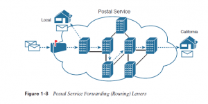
Still thinking about the postal service, consider the difference between the person sending the letter and therefore the work that the postal service does. The person sending the letters expects that the postal service will deliver the letter most of the time. However, the person sending the letter doesn’t got to know the details of exactly what path the letters take. In contrast, the postal service doesn’t create the letter, but it accepts the letter from the customer.
Then, the postal service must know the details about addresses and postal codes that group addresses into larger groups, and it must have the ability to deliver the letters.
The TCP/IP application and transport layers act just like the person sending letters through the postal service. These upper layers work an equivalent way regardless of whether the endpoint host computers are on an equivalent LAN or are separated by the whole Internet. To send a message, these upper layers ask the layer below them, the network layer, to deliver the message.
“Network layer Provide switching technologies and routing technologies”
The lower layers of the TCP/IP model act more just like the postal service to deliver those messages to the correct destinations. To do so, these lower layers must understand the underlying physical network because they need to choose how to best deliver the data from one host to a different So, what does this all matter to networking? Well, the network layer of the TCP/IP networking model, primarily defined by the internet Protocol (IP), works very similar to the postal service. IP defines that every host computer should have a different IP address, even as the mail defines addressing that allows unique addresses for every house, apartment, and business. Similarly, IP defines the process of routing in order that devices called routers can work just like the post office, forwarding packets of data in order that they’re delivered to the correct destinations. even as the postal service created the required infrastructure to deliver letters—post offices, sorting machines, trucks, planes, and personnel—the network layer defines the details of how a network infrastructure should be created in order that the network can deliver data to all computers within the network.
Internet Protocol Addressing Basics
IP defines addresses for several important reasons. First, each device that uses TCP/IP— each TCP/IP host—needs a unique address in order that it can be identified within the network. IP also defines how to group addresses together, a bit like the postal system groups addresses supported postal codes (like ZIP codes within the United States).
To understand the basics, examine Figure 1-9, which shows the familiar web server Larry and browser Bob; but now, instead of ignoring the network between these two computers, a part of the network infrastructure is included.
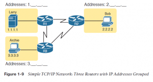 First, note that Figure 1-9 shows some sample IP addresses. Each IP address has four numbers, separated by periods. during this case, Larry uses IP address 1.1.1.1, and Bob uses 2.2.2.2.
This style of number is named a dotted-decimal notation (DDN). Figure 1-9 also shows three groups of addresses. during this example, all IP addresses that begin with 1 must be on the upper left, as shown in shorthand within the figure as 1. . . .
All addresses that begin with 2 must be on the right, as shown in shorthand as 2. . . . Finally, all IP addresses that begin with 3 must be at the bottom of the figure. additionally , Figure 1-9 introduces icons that represent IP routers. Routers are networking devices that connect the parts of the TCP/IP network together for the aim of routing (forwarding) IP packets to the correct destination. Routers do the equivalent of the work done by each post office site: They receive IP packets on various physical interfaces, make decisions supported the IP address included with the packet, then physically forward the packet out another network interface.
IP Routing Basics
The TCP/IP network layer, using the IP protocol, provides a service of forwarding IP packets from one device to a different . Any device with an IP address can connect to the TCP/IP network and send packets. This section shows a basic IP routing example for perspective.
Figure 1-10 repeats the familiar case during which web server Larry wants to send a part of a web page to Bob, but now with details related to IP. On the lower left, note that server Larry has the familiar application data, HTTP header, and TCP header ready to send. additionally , the message now contains an IP header. The IP header includes a source IP address of Larry’s IP address (1.1.1.1) and a destination IP address of Bob’s IP address (2.2.2.2).
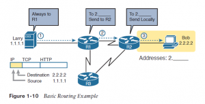 Step 1, on the left of Figure 1-10, begins with Larry being ready to send an IP packet. Larry’s IP process chooses to send the packet to some router—a nearby router on an equivalent LAN—with the expectation that the router will know how to forward the packet. (This logic is much such as you or me sending all our letters by putting them during a nearby mailbox.)
Larry doesn’t got to know anything more about the topology or the opposite routers. At Step 2, Router R1 receives the IP packet, and R1’s IP process makes a decision. R1 looks at the destination address (2.2.2.2), compares that address to its known IP routes, and chooses to forward the packet to Router R2. This process of forwarding the IP packet is called IP routing (or simply routing).
At Step 3, Router R2 repeats an equivalent kind of logic used by Router R1. R2’s IP process will compare the packet’s destination IP address (2.2.2.2) to R2’s known IP routes and make a choice to forward the packet to the right, on to Bob. you’ll learn IP to more depth than the other protocol while preparing for CCENT and CCNA. Practically half the chapters during this book discuss some feature that relates to addressing, IP routing, and how routers perform routing.
TCP/IP Link Layer (Data Link Plus Physical)
The TCP/IP model’s original link layer defines the protocols and hardware required to deliver data across some physical network. The term link refers to the physical connections, or links, between two devices and therefore the protocols used to control those links. a bit like every layer in any networking model, the TCP/IP link layer provides services to the layer above it within the model. When a host’s or router’s IP process chooses to send an IP packet to a different router or host, that host or router then uses link-layer details to send that packet to the next host/router.
Because each layer provides a service to the layer above it, take a moment to think about the IP logic related to Figure 1-10. in that example, host Larry’s IP logic chooses to send the IP packet to a close-by router (R1), with no mention of the underlying Ethernet. The Ethernet network, which implements link-layer protocols, must then be used to deliver that packet from host Larry over to router R1. Figure 1 11 shows four steps of what occurs at the link layer to allow Larry to send the IP packet to R1.
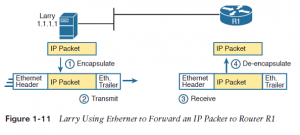 Figure 1-11 shows four steps. the first two occur on Larry, and therefore the last two occur on Router R1, as follows:
Step 1. Larry encapsulates the IP packet between an Ethernet header and Ethernet trailer, creating an Ethernet frame.
Step 2. Larry physically transmits the bits of this Ethernet frame, using electricity flowing over the Ethernet cabling.
Step 3. Router R1 physically receives the electrical signal over a cable, and re-creates an equivalent bits by interpreting the meaning of the electrical signals.
Step 4. Router R1 de-encapsulates the IP packet from the Ethernet frame by removing and discarding the Ethernet header and trailer.
By the end of this process, the link-layer processes on Larry and R1 have worked together to deliver the packet from Larry to Router R1.
The link layer includes a large number of protocols and standards. for instance , the link layer includes all the variations of Ethernet protocols, along side several other LAN standards that were more popular in decades past. The link layer includes wide-area network (WAN) standards for various physical media, which differ significantly compared to LAN standards due to the longer distances involved in transmitting the data. This layer also includes the popular WAN standards that add headers and trailers as shown generally in Figure 1-11—protocols such as the Point-to-Point Protocol (PPP) and Frame Relay. Chapter 2, “Fundamentals of Ethernet LANs,” and Chapter 3, “Fundamentals of WANs,” further develop these topics for LANs and WANs, respectively.
In short, the TCP/IP link layer includes two distinct functions: functions related to the physical transmission of the data, plus the protocols and rules that control the use of the physical media. The five-layer TCP/IP model simply splits out the link layer into two layers (data link and physical) to match this logic.
Questions related to this topic
- What are the protocols used in TCP IP?
- What are the five layers of TCP IP protocol suite?
- What are the five layers of Internet protocol stack?
- What happens in each layer of the TCP IP protocol stack?
This Blog Article is posted by
Infosavvy, 2nd Floor, Sai Niketan, Chandavalkar Road Opp. Gora Gandhi Hotel, Above Jumbo King, beside Speakwell Institute, Borivali West, Mumbai, Maharashtra 400092
Contact us – www.info-savvy.com