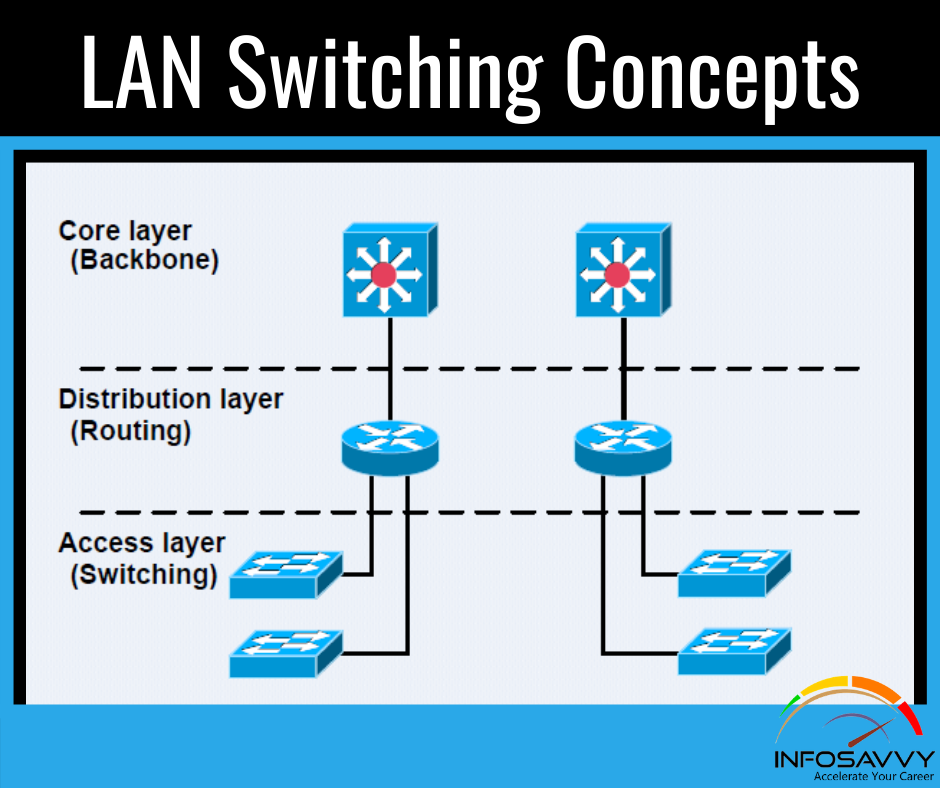
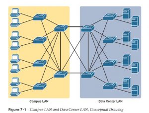
LAN Switching Concepts A modern Ethernet LAN connects user devices also as servers into some switches, with the switches then connecting to every other, sometimes during a design like Figure 7-1. a part of the LAN, called a campus LAN, supports the end user population as shown on the left of the figure. user devices connect to LAN switches, which in turn connect to other switches so that a path exists to the rest of the network. The campus LAN switches sit in wiring closets close to the end users. On the right, the servers wont to provide information to the users also connects to the LAN. Those servers and switches often sit during a closed room called a data center, with connections to the campus LAN to support traffic to/from the users.
To forward traffic from a user device to a server and back, each switch performs the same kind of logic, independently from one another . the primary half this chapter examines the logic: how a switch chooses to forward an Ethernet frame, when the switch chooses to not forward the frame, and so on.
Overview of Switching Logic
Ultimately , the role of a LAN switch is to forward Ethernet frames. LANs exist as a group of user devices, servers, and other devices that connect to switches, with the switches connected to every other. The LAN switch has one primary job: to forward frames to the right destination (MAC) address. And to realize that goal, switches use logic—logic based on the source and destination MAC address in each frame’s Ethernet header.
LAN switches receive Ethernet frames then make a switching decision: either forward the frame out another ports or ignore the frame. To accomplish this primary mission, switches perform three actions:
- Deciding when to forward a frame or when to filter (not forward) a frame, based on the destination MAC address
- Preparing to forward frames by learning MAC addresses by examining the source MAC address of every frame received by the switch
- Preparing to forward just one copy of the frame to the destination by creating a (Layer 2) loop-free environment with other switches by using Spanning Tree Protocol (STP) the primary action is that the switch’s primary job, whereas the opposite two items are overhead functions.
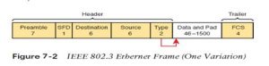
Although Chapter 2’s section titled “Ethernet Data-Link Protocols” already discussed the frame format, this discussion of Ethernet switching is pretty important, so reviewing the Ethernet frame at now could be helpful. Figure 7-2 shows one popular format for an Ethernet frame. Basically, a switch would take the frame shown within the figure, make a choice of where to forward the frame, and send the frame out that other interface.
Also Read : Verifying and Analyzing Ethernet Switching
Forwarding Known Unicast Frames
To decide whether to forward a frame, a switch uses a dynamically built table that lists MAC addresses and outgoing interfaces. Switches compare the frame’s destination MAC address to the present table to make a decision whether the switch should forward a frame or just ignore it. for instance , consider the simple network shown in Figure 7-3, with Fred sending a frame to Barney.
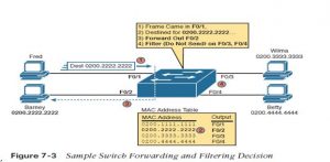
In this figure, Fred sends a frame with destination address 0200.2222.2222 (Barney’s MAC address). The switch compares the destination MAC address (0200.2222.2222) to the MAC address table, matching the bold table entry. That matched table entry tells the switch to forward the frame out port F0/2, and only port F0/2.
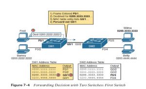
A switch’s MAC address table lists the situation of every MAC relative thereto one switch. In LANs with multiple switches, each switch makes an independent forwarding decision supported its own MAC address table. Together, they forward the frame so that it eventually arrives at the destination.
For example, Figure 7-4 shows the primary switching decision during a case during which Fred sends a frame to Wilma, with destination MAC 0200.3333.3333. The topology has changed versus the previous figure, this point with two switches, and Fred and Wilma connected to 2 different switches. Figure 7-3 shows the primary switch’s logic, in reaction to Fred sending the first frame. Basically, the switch receives the frame port F0/1, finds the destination MAC (0200.3333.3333) within the MAC address table, sees the outgoing port of G0/1, so SW1 forwards the frame out its G0/1 port.
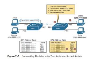
That same frame next arrives at switch SW2, entering SW2’s G0/2 interface. As shown in Figure 7-5, SW2 uses the same logic steps, but using SW2’s table. The MAC table lists the forwarding instructions for that switch only. In this case, switch SW2 forwards the frame out its F0/3 port, based on SW2’s MAC address table.
The examples so far use switches that happen to have a MAC table with all the MAC addresses listed. As a result, the destination MAC address in the frame is known to the switch. The frames are called known unicast frames, or simply known unicasts, because the destination address is a unicast address, and the destination is known. As shown in these examples, switches forward known unicast frames out one port: the port as listed in the MAC table entry for that MAC address.
Questions related to this topic
- What information does a switch use to forward Ethernet frames?
- Do Ethernet switches have MAC addresses?
- How do Ethernet switches know where to send the frames they receive?
- Does it matter what port you use on a switch?
This Blog Article is posted by
Infosavvy, 2nd Floor, Sai Niketan, Chandavalkar Road Opp. Gora Gandhi Hotel, Above Jumbo King, beside Speakwell Institute, Borivali West, Mumbai, Maharashtra 400092
Contact us – www.info-savvy.com