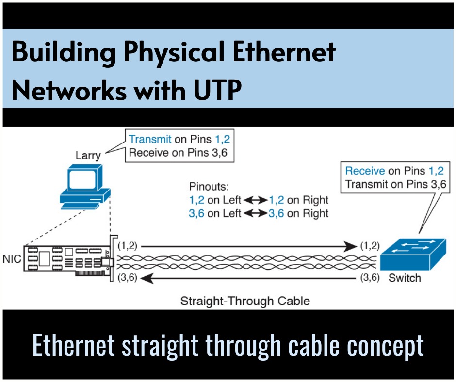
For this second of three major sections of this chapter, I focus on the individual physical links between any two Ethernet nodes. Before the Ethernet network as an entire can send Ethernet frames between user devices, each node must be ready and ready to send data over an individual physical link. This section looks at some of the particulars of how Ethernet sends data over these links. This section focuses on the three most ordinarily used Ethernet standards: 10BASE-T (Ethernet), 100BASE-T (Fast Ethernet, or FE), and 1000BASE-T (Gigabit Ethernet, or GE). Specifically, this section looks at the details of sending data in both directions over a UTP cable. It then examines the specific wiring of the UTP cables used for 10-Mbps, 100-Mbps, and 1000-Mbps Ethernet.
Transmitting Data Using Twisted Pairs
While it’s true that Ethernet sends data over UTP cables, the physical means to send the data uses electricity that flows over the wires inside the UTP cable. to better understand how Ethernet sends data using electricity, break the thought down into two parts: how to create an electrical circuit then how to make that electrical signal communicate 1s and 0s. First, to make one circuit , Ethernet defines how to use the two wires inside one twisted pair of wires, as shown in Figure 2-5. The figure doesn’t show a UTP cable between two nodes, but instead shows two individual wires that are inside the UTP cable. An electrical circuit requires an entire loop, therefore the two nodes, using circuitry on their Ethernet ports, connect the wires in one pair to finish a loop, allowing electricity to flow.

To send data, the two devices follow some rules called an encoding scheme. the thought works tons like when two people talk using the same language: The speaker says some words during a particular language, and therefore the listener, because she speaks the same language, can understand the spoken words. With an encoding scheme, the transmitting node changes the electrical signal over time, while the other node, the receiver, using the same rules, interprets those changes as either 0s or 1s. (For example, 10BASE-T uses an encoding scheme that encodes a binary 0 as a transition from higher voltage to lower voltage during the middle of a 1/10,000,000th-of-a-second interval.) Note that in an actual UTP cable, the wires will be twisted together, rather than being parallel as shown in Figure 2-5. The twisting helps solve some important physical transmission issues. When electrical current passes over any wire, it creates electromagnetic interference (EMI) that interferes with the electrical signals in nearby wires, including the wires within the same cable. (EMI between wire pairs within the same cable is named crosstalk.) Twisting the wire pairs together helps cancel out most of the EMI, so most networking physical links that use copper wires use twisted pairs.
Breaking Down a UTP Ethernet Link
The term Ethernet link refers to any physical cable between two Ethernet nodes. to learn about how a UTP Ethernet link works, it helps to break down the physical link into those basic pieces, as shown in Figure 2-6: the cable itself, the connectors on the ends of the cable, and therefore the matching ports on the devices into which the connectors are going to be inserted.

First, think about the UTP cable itself. The cable holds some copper wires, grouped as twisted pairs. The 10BASE-T and 100BASE-T standards require two pairs of wires, while the 1000BASE-T standard requires four pairs. Each wire features a color-coded plastic coating, with the wires during a pair having a colour scheme . for instance , for the blue wire pair, one wire’s coating is all blue, while the opposite wire’s coating is blue-and-white striped. Many Ethernet UTP cables use an RJ-45 connector on both ends. The RJ-45 connector has eight physical locations into which the eight wires within the cable can be inserted, called pin positions, or simply pins. These pins create an area where the ends of the copper wires can touch the electronics inside the nodes at the end of the physical link so that electricity can flow.
To complete the physical link, the nodes each need an RJ-45 Ethernet port that matches the RJ-45 connectors on the cable in order that the connectors on the ends of the cable can connect to each node. PCs often include this RJ-45 Ethernet port as part of a network interface card (NIC), which may be an expansion card on the PC or are often inbuilt to the system itself. Switches typically have many RJ-45 ports because switches give user devices a place to attach to the Ethernet LAN. Figure 2-7 shows photos of the cables, connectors, and ports.

The figure shows a connector on the left and ports on the right. The left shows the eight pin positions within the end of the RJ-45 connector. The upper right shows an Ethernet NIC that’s not yet installed during a computer. The lower-right part of the figure shows the side of a Cisco 2960 switch, with multiple RJ-45 ports, allowing multiple devices to simply connect to the Ethernet network.
Finally, while RJ-45 connectors with UTP cabling are often common, Cisco LAN switches often support other sorts of connectors also . when you buy one among the various models of Cisco switches, you need to believe the mix and numbers of every type of physical ports you would like on the switch.
To give its customers flexibility on the type of Ethernet links, even after the customer has bought the switch, Cisco switches include some physical ports whose port hardware (the transceiver) are often changed later, after you buy the switch.
For example, Figure 2-8 shows a photograph of a Cisco switch with one of the swappable transceivers. in this case, the figure shows an enhanced small form-factor pluggable (SFP+) transceiver, which runs at 10 Gbps, just outside two SFP+ slots on a Cisco 3560CX switch. The SFP+ itself is that the silver colored part below the switch, with a black cable connected to it.

This Blog Article is posted by
Infosavvy, 2nd Floor, Sai Niketan, Chandavalkar Road Opp. Gora Gandhi Hotel, Above Jumbo King, beside Speakwell Institute, Borivali West, Mumbai, Maharashtra 400092
Contact us – www.info-savvy.com


